Installing a 100 Amp Sub Panel in a Detached Garage: DIY Step-by-Step Guide
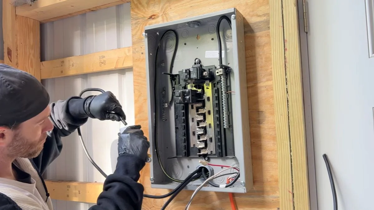
Installing a 100 amp sub panel in a detached garage is a project most skilled homeowners can complete legally and safely — but only if they nail wire sizing, grounding, and NEC Article 225 compliance from the start.
The real problem is confidence: you know enough to attempt the work, but one mistake on neutral-ground bonding, conductor sizing, or the permit application can mean a failed inspection, a fire hazard, or a forced tear-out.
This guide walks you through every stage — load calculations, wire selection, conduit routing, panel wiring, and inspection preparation — so you leave with a code-compliant, fully functional subpanel and the documentation to prove it.
Why Wire Size and Distance Matter
Wire gauge is not just about amperage — distance is equally critical. A feeder wire that’s correctly sized for 100 amps at 50 feet can cause dangerous voltage drop at 150 feet, reducing available power and creating heat inside the conductor. Undersized wire is both a fire hazard and a direct NEC violation.
A 4-conductor feed is required for any detached garage subpanel. That means two hots, one neutral, and one separate ground — never a 2-conductor or 3-conductor cable. Detached structures require an independent ground per NEC Article 225.30, which also governs the number of supplies permitted to a separate building.
Calculating Wire Size: Formula and Real Examples
The standard voltage drop formula is: VD = (2 × L × I × R) / 1000
Where L is the one-way run length in feet, I is the current in amps, and R is the resistance per 1,000 feet of conductor (from NEC Chapter 9 tables).
NEC Article 210.19 sets the acceptable voltage drop benchmark at 3% for feeder circuits, with a 5% combined maximum across the full system. Staying within 3% on a 240V feeder means keeping drop below 7.2 volts.
Here’s how run length changes your wire requirements for a 100-amp feeder:
| Run Length | Aluminum AWG | Copper AWG |
|---|---|---|
| 50 ft | 2 AWG | 4 AWG |
| 100 ft | 2/0 AWG | 1/0 AWG |
| 150 ft | 3/0 AWG | 2/0 AWG |
Aluminum is code-legal and widely used for feeder wire in conduit — it costs significantly less than copper at these gauges. Use a voltage drop calculator like the one at Southwire.com to verify your specific run before purchasing wire.
NEC Code Compliance and Disconnecting Means
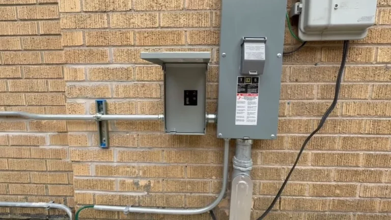
NEC Article 225 governs all electrical installations to detached structures, including garages and workshops. Two rules from this article are non-negotiable: every detached garage must have a disconnecting means, and that disconnect must be located at the structure — not at the main panel.
The disconnect can be the main breaker built into the subpanel itself, or a separate service disconnect switch mounted near the panel. It must be readily accessible, within sight of the subpanel, and capable of being locked in the open position. A 100-amp breaker inside a main-breaker-style subpanel satisfies this requirement cleanly and is the most common DIY approach.
Before you pull a single wire, check with your local Authority Having Jurisdiction (AHJ) — the municipal or county office that issues permits. Most jurisdictions require a permit for this work, and nearly all require a licensed electrician or inspector to sign off on the final installation. Skipping the permit creates liability issues during home sales and voids homeowner’s insurance coverage for fire damage.
Grounding and Bonding: Equipment and Electrode Requirements
Grounding a detached garage subpanel is fundamentally different from wiring a subpanel inside the same building as the main panel. At a detached structure, the neutral and ground buses must be kept separate — they are only bonded at the main service panel.
The equipment grounding conductor must be the same gauge as the feeder neutral. For a 100-amp feeder, that means a minimum 4 AWG copper ground wire running back to the main panel’s grounding system.
The garage also needs its own grounding electrode system. Drive a copper-clad ground rod to a minimum depth of 8 feet. If soil resistance is high — common in dry or rocky soil — NEC 250.53 requires a second rod spaced at least 6 feet away. Connect the rod to the subpanel’s ground bus with a 6 AWG bare copper conductor minimum, per NEC 250.66.
Do not bond the neutral bar to the ground bar inside the subpanel. That connection belongs only at the main service entrance. Incorrect bonding here creates parallel neutral paths, which causes shock hazards and trips GFCI devices unpredictably.
Installation Materials and Underground Conduit Specs
Choosing the right materials before you dig saves costly rework. The conduit type, wire insulation rating, and burial depth all interact — get one wrong and you face either a code violation or a premature failure underground where repairs are expensive.
Feeder Cable, Conduit, and Disconnect Components
The subpanel itself should be rated for at least 100 amps with a main breaker included. For outdoor or garage mounting, choose a panel with a NEMA 3R enclosure rating minimum — this protects against rain and sleet. In coastal or high-humidity environments, step up to NEMA 4X for corrosion resistance.
For wire inside conduit on an underground run, use conductors rated USE-2, RHH, or RHW-2. These insulation types handle moisture and direct burial conditions. Standard NM-B (Romex) is never permitted underground or in conduit feeding a detached structure.
Conduit material comes down to two practical choices:
- Schedule 40 PVC: Lower cost, corrosion-proof, easier to work with — the standard choice for most residential underground runs
- Rigid Metal Conduit (RMC): More durable above ground, required in some high-traffic or exposed areas, but costs significantly more and requires threading tools
For a 100-amp feeder with 2/0 aluminum or 1/0 copper conductors plus a ground, a 2-inch conduit satisfies the NEC 40% conduit fill rule. Use a conduit fill calculator at Southwire.com or the NEC Chapter 9 tables to confirm your specific conductor combination.
Burial Depth and Protection Standards
NEC Table 300.5 sets the minimum burial depth at 18 inches for conductors in PVC conduit on residential properties. Rigid metal conduit requires only 6 inches of cover — useful when you need a shallow crossing under a concrete apron or driveway.
For runs under driveways or high-traffic areas, concrete encasement at 12 inches depth is a code-accepted alternative to deeper burial. Many inspectors prefer it for added mechanical protection.
Above-ground conduit must be secured every 3 feet and within 3 feet of every box or enclosure. At the entry and exit points where conduit transitions into the panel or exits the ground, use conduit bushings to protect wire insulation from sharp edges, and seal all underground conduit entries with an approved duct seal compound to block moisture and pests.
Step-by-Step Installation Sequence
Work through this sequence in order. Skipping steps or reversing the sequence — especially energizing the feeder before grounding is complete — creates serious shock and fire risk.
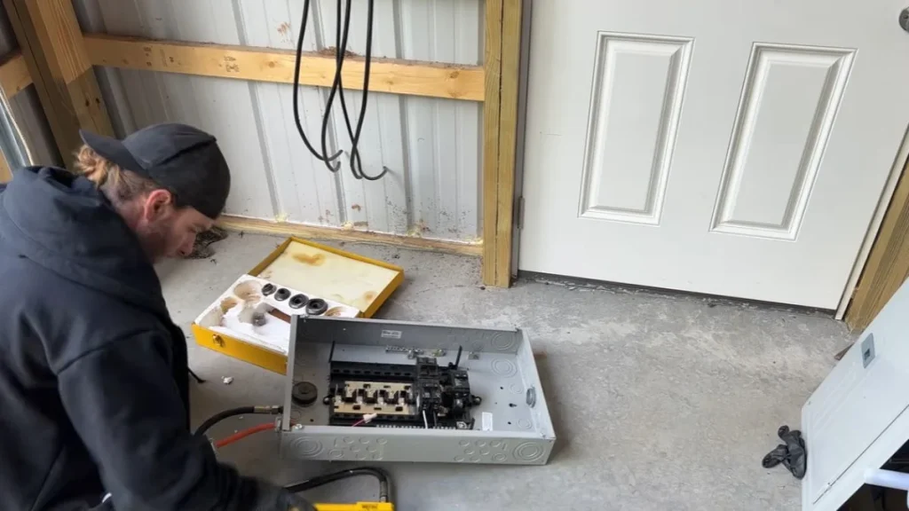
Preparing and Running the Feeder
Start with these pre-installation steps before touching a shovel or wire:
- Measure the exact one-way distance from the main panel to the garage subpanel location
- Run the voltage drop calculation and confirm your wire gauge selection
- Pull your permit from the local AHJ and confirm inspection requirements
- Purchase all conduit, fittings, wire, the subpanel, and ground rods before starting
Dig the trench to a minimum 18-inch depth along the planned route. Remove sharp rocks from the trench bottom — they can damage conduit over time through soil movement. Lay the conduit run, gluing all PVC joints, and secure above-ground sections to the structure every 3 feet using conduit straps.
Pulling wire through a long conduit run requires wire-pulling lubricant — a product like Ideal Yellow 77 reduces friction significantly on runs over 50 feet. Pull all 4 conductors simultaneously to avoid binding. Leave at least 12 inches of extra wire at each end for terminal connections.
Sub Panel Connection and Testing
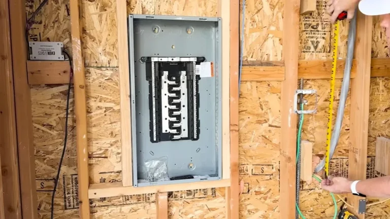
Mount the subpanel on a solid interior wall of the garage or in a weatherproof enclosure if exposed. The panel must be accessible and mounted at a height where the center of the highest breaker is no more than 6 feet 7 inches from the floor, per NEC 240.24.
Connect the feeder conductors in this order:
- Ground conductor to the equipment grounding bus first
- Neutral conductor to the neutral bus (isolated from ground bus)
- Hot conductors to the main breaker lugs
Torque all terminals to the manufacturer’s specification — typically 125 in-lb for main lug connections on 100-amp panels. Under-torqued connections are a leading cause of arcing and panel fires.
Drive the ground rod to full 8-foot depth and connect it to the equipment grounding bus with 6 AWG bare copper. Keep the neutral bar and ground bar completely separate inside this subpanel.
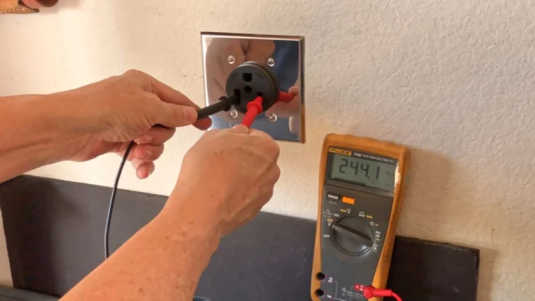
After energizing, use a clamp meter to confirm load balance across both hot legs. Test ground resistance with a ground resistance tester — the IEEE standard target is below 5 ohms. Any reading above 25 ohms requires a second ground rod per NEC 250.53.
Once the panel itself is in place, here’s how to run the subpanel wiring.
Know When to Call a Licensed Electrician
A permit and inspection are not optional extras — they are the legal mechanism that confirms your installation is safe and protects your home’s insurability. If your AHJ mandates a licensed electrician to pull the permit, requires professional sign-off on bonding calculations, or your ground resistance test exceeds 25 ohms after two rods, stop and bring in a pro. Start today by calling your local AHJ to confirm permit requirements before purchasing a single material.