How to Install a Subpanel in a Detached Garage: Code-Compliant Guide
Installing a subpanel in a detached garage follows different NEC rules than work on an attached addition — specifically NEC Article 225, which governs outside branch circuits and feeders for separate structures.
Most homeowners with main panel experience hit a wall at the detached-specific requirements: the mandatory 4-wire feeder, separate grounding electrode system, correct breaker sizing, and underground conduit depth rules that don’t apply to interior work.
This guide walks you through every step — feeder sizing, conduit routing, grounding, and code compliance — so you finish with a permitted, inspector-approved subpanel that safely powers your garage.
Why Detached Garages Need Different Rules
A detached garage is treated as a separate structure under NEC Article 225, which means it needs its own grounding electrode system — typically a ground rod driven at least 8 feet into the earth at the garage itself.
The 4-Wire Feeder Requirement
Attached additions can share the ground and neutral on a 3-wire feeder back to the main panel. Detached structures cannot. NEC 225.30 and 250.32 require a 4-wire feeder — two hots, one neutral, and one separate equipment ground — running from the main panel to the garage subpanel. This keeps the neutral and ground conductors isolated at the subpanel, which is a hard code requirement, not a suggestion.
Here’s why it matters. If the neutral and ground bond together at a detached subpanel (as they do at the main service entrance), fault current can travel back on the ground wire and through any metal path between structures — including water pipes, gas lines, or even a wet dog running between the buildings. That’s a real electrocution hazard.
Ground and Neutral Must Stay Separated
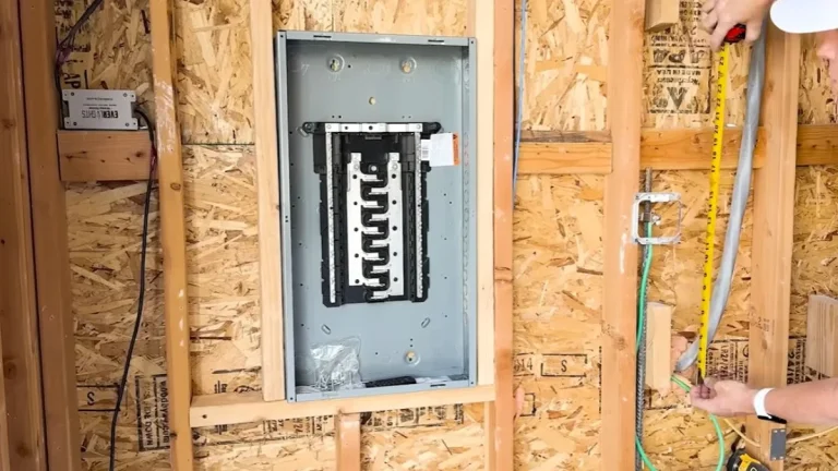
At the garage subpanel, the neutral bar and the ground bar must be separate and unbonded. Remove the bonding jumper — the green screw or metal strap that connects neutral to ground — before energizing the panel. Most subpanel manufacturers ship the panel with this jumper installed, so removing it is a step many DIYers miss.
Your Own Grounding Electrode System
The detached structure needs at least one ground rod connected to the subpanel’s ground bar. This grounding electrode system works alongside the equipment ground wire in the feeder, giving fault current two return paths and keeping the structure’s metal components at safe voltage levels.
Sizing and Selecting Your Subpanel
Choosing the wrong amp rating means either tripping breakers under load or paying to redo the feeder run in two years. Size it right the first time by calculating what you actually plan to run.
Load Calculation Basics for Garage Equipment
Add up the wattage of every circuit you plan to install. Common garage loads include:
- A 20-amp, 240V air compressor (roughly 3,800 watts at startup)
- A MIG welder like the Lincoln Electric 210 MP (up to 4,400 watts)
- A Level 2 EV charger such as the ChargePoint Home Flex (up to 9,600 watts at 40 amps)
- Lighting and receptacle circuits (typically 1,500–2,000 watts combined)
Apply the 80% rule to any continuous load — one that runs for 3 hours or more. A 40-amp EV charger circuit requires a 50-amp breaker and 50-amp-rated wire to stay code-compliant under NEC 210.19.
Comparing 50-Amp, 60-Amp, and 100-Amp Options
| Amp Rating | Best For | Feeder Wire Gauge | Typical Breaker Cost |
|---|---|---|---|
| 50-amp | Basic lighting, small tools | 6 AWG copper | $15–$30 |
| 60-amp | Most garages, future expansion | 6 AWG copper | $20–$40 |
| 100-amp | Welders, EV chargers, simultaneous heavy loads | 4 AWG copper or 2 AWG aluminum | $40–$80 |
A 60-amp subpanel handles most hobbyist garages comfortably. Step up to 100 amps if you plan to run an EV charger alongside a welder or compressor simultaneously. The feeder wire gauge and conduit size both increase with amperage, which affects underground conduit run cost more than anything else.
If you’re deciding on panel size first, here’s a full breakdown for a 100-amp setup specifically.
Four-Wire Feeder: The Critical Detached Garage Requirement
The single biggest mistake in detached garage subpanel work is running a 3-wire feeder instead of 4 wires. NEC 250.32(B) prohibits sharing the neutral and ground in a separate structure feeder — full stop.
Why Detached Structures Mandate Separate Neutral and Ground
In your main panel, the neutral and ground bond together at one point — the main bonding jumper. That’s the only place this connection is legal. At a detached subpanel, the neutral bar and ground bar must remain completely separate and unbonded.
The 4-wire feeder carries:
- Hot 1 — 120V leg A
- Hot 2 — 120V leg B
- Neutral — carries unbalanced current back to main panel
- Equipment ground — fault-current return path, never carries current under normal operation
The ground wire in the feeder works alongside the garage’s own grounding electrode system — typically a driven ground rod — to give the structure a complete, code-compliant grounding setup under NEC Article 250.
Wire Gauge and Distance Calculations
Wire gauge determines both safe ampacity and voltage drop over the feeder run. Use these as your baseline:
| Feeder Amperage | Distance Under 100 ft | Distance Over 100 ft |
|---|---|---|
| 50-amp | 8 AWG copper | 6 AWG copper |
| 60-amp | 6 AWG copper | 4 AWG copper |
| 100-amp | 4 AWG copper | 2 AWG copper or larger |
Voltage drop becomes a real problem beyond 100 feet. The NEC recommends keeping voltage drop under 3% for branch circuits and 5% total. At 100 feet on a 60-amp, 240V feeder, 6 AWG copper sits right at the edge. Use the voltage drop calculator at Southwire.com to verify your specific run before purchasing wire. Aluminum feeder wire is code-acceptable and significantly cheaper for 100-amp runs — just use Noalox anti-oxidant compound on every aluminum connection.
Running Feeder Lines: Underground vs. Overhead
How you route the feeder from your main panel to the garage subpanel affects cost, code compliance, and long-term reliability more than almost any other decision in this project.
Underground Conduit: Burial Depth and Material
NEC Table 300.5 sets minimum burial depths based on conduit type:
| Conduit Type | Minimum Burial Depth |
|---|---|
| Rigid Metal Conduit (RMC) | 6 inches |
| PVC Schedule 80 | 18 inches |
| PVC Schedule 40 | 24 inches |
| Direct-burial cable (no conduit) | 24 inches |
Always call 811 — the national “Call Before You Dig” service — at least 3 business days before trenching. Striking a buried gas or water line is dangerous and exposes you to liability.
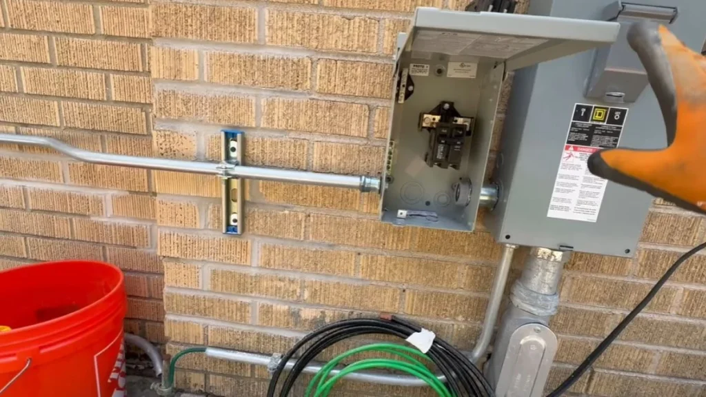
PVC Schedule 40 is the most common choice for DIYers: it’s inexpensive, easy to glue, and available at any home center. Use rigid metal conduit where the feeder transitions from underground to above-grade at both the main panel and garage entry points — RMC handles physical damage that PVC cannot.
Overhead Routing: Clearance Requirements
Overhead feeders are faster and cheaper to install but face strict NEC 225.18 clearance rules:
- 10 feet above finished grade (minimum, pedestrian areas)
- 12 feet above residential driveways
- 18 feet above public roads or commercial driveways
- 3 feet of clearance from rooflines and windows
Overhead runs require a weatherhead, drip loop, and proper strain relief at both ends. Spans longer than 50 feet need a messenger wire for physical support. Most inspectors prefer underground runs in residential applications — and some jurisdictions mandate them outright for new construction. Check with your local building department before committing to aerial routing.
Grounding and Bonding the Detached Subpanel
Grounding errors are the most common reason detached garage subpanel installations fail inspection — and the most dangerous to leave uncorrected. Get this right before the panel is ever energized.
Ground Rod Installation and Continuity
Drive at least one copper-clad or galvanized steel ground rod a minimum of 8 feet into the earth at the garage, as required by NEC 250.53. If the soil is rocky and you can’t achieve 8 feet of depth, NEC allows horizontal burial at 30 inches minimum as an alternative.
Use a #6 AWG bare copper wire to connect the ground rod to the subpanel’s ground bar. If your feeder is 100 amps, step up to #4 AWG for the grounding electrode conductor — the size must match NEC Table 250.66 based on your feeder conductor size, not the breaker rating.
Apply Noalox or Ilsco DeOx anti-oxidant compound to every ground rod connection and any aluminum conductor termination. This prevents corrosion from degrading the connection over time.
Separate Ground vs. Bonded Neutral: The Critical Distinction
At the main panel, the neutral and ground bond together — that’s the service entrance bonding point, and it’s intentional. At the detached subpanel, they must never bond.
Here’s what to check before closing up the panel:
- The green bonding screw must be removed from the neutral bar
- The neutral bar must float independently on its insulated standoffs
- The ground bar connects only to the feeder’s equipment ground wire and the ground rod conductor
- Neutral conductors from branch circuits land on the neutral bar only
Leaving the bonding jumper installed at the subpanel creates a parallel neutral path back through the ground wire and the earth — a code violation that causes nuisance tripping, stray voltage, and genuine shock hazard. Every inspector checks this first.
Main Panel Breaker and Feeder Connection
Work at the main panel carries real risk — the service entrance lugs remain live even with the main breaker off. If you’re not comfortable working near energized conductors, hire a licensed electrician for this specific step. Everything else in this project is safer; this part is not.
Selecting the Right Two-Pole Breaker
The breaker in the main panel must match both the wire gauge and the subpanel’s amp rating. A 60-amp subpanel fed with 6 AWG copper needs a 60-amp two-pole breaker. Use a breaker from the same manufacturer as your main panel — Square D QO breakers in a QO panel, Eaton BR breakers in a BR panel. Cross-brand breakers are a code violation under NEC 110.3(B) unless explicitly listed for that panel.
Check that your main panel has two adjacent open slots. A tandem or half-size breaker is not acceptable for a feeder circuit.
Installing the Breaker and Terminating Feeder Conductors
Follow this sequence at the main panel:
- Turn off the main breaker
- Remove the panel cover — confirm service lugs are still live with a non-contact voltage tester
- Snap the two-pole breaker into the open slots, seating it firmly on both bus bars
- Strip feeder conductors to the manufacturer’s specified strip length — typically 3/4 to 1 inch
- Insert Hot 1 and Hot 2 into the breaker lugs, one conductor per lug
- Land the neutral on the main panel’s neutral bar
- Land the equipment ground on the main panel’s ground bar
Torque Specifications Matter
Hand-tight is never enough. Under-torqued connections arc and overheat. Every breaker and lug has a torque spec printed on the device or in its spec sheet — a 60-amp Square D QO breaker requires 35 lb-in on its terminals. Use a calibrated torque screwdriver, not a standard driver, for every connection in both the main panel and the subpanel.
NEC Code Compliance and Permit Requirements
Skipping the permit on a detached garage subpanel is a calculated risk with real consequences — failed home sale inspections, voided homeowner’s insurance, and personal liability if a fire starts at an unpermitted panel.
NEC Article 225 Requirements for Detached Structures
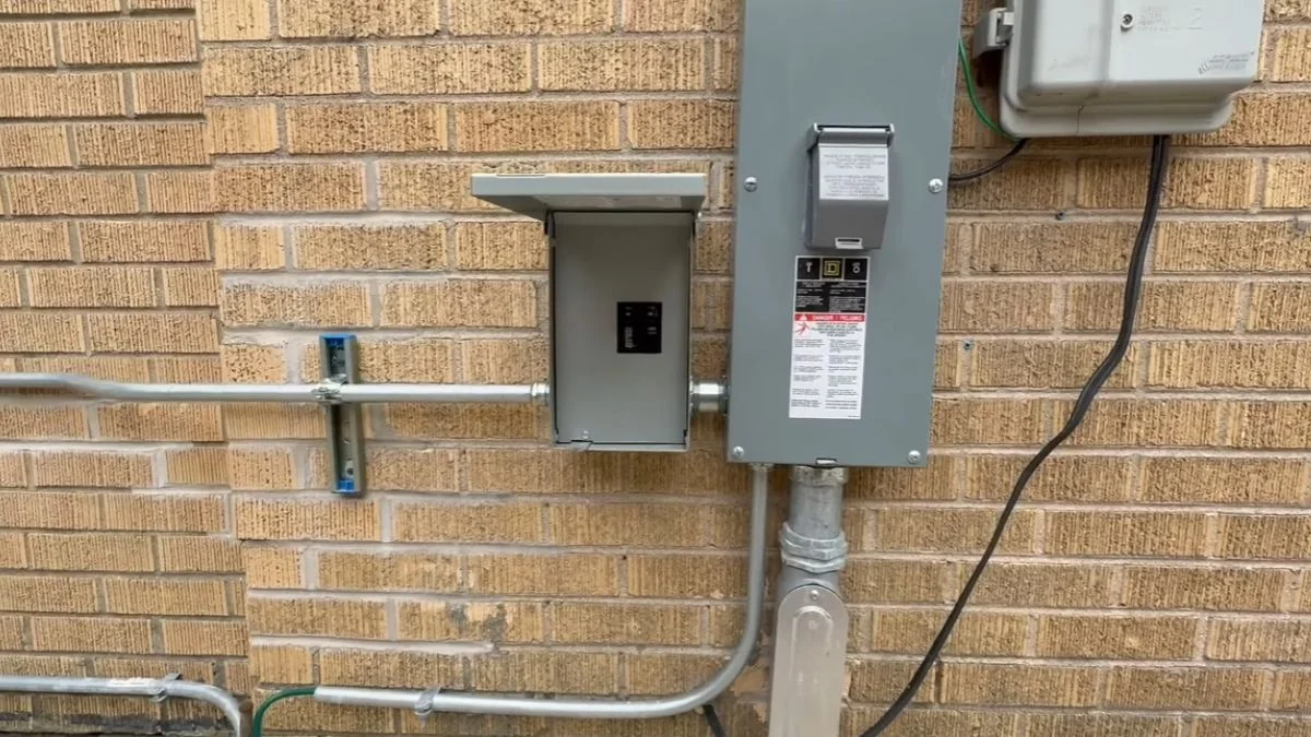
Article 225 mandates a disconnect means at the detached structure itself. This means the subpanel must have a main breaker — you cannot rely on the two-pole feeder breaker back at the main panel as the garage disconnect. Most pre-built subpanels sold as “main breaker panels” satisfy this requirement automatically. A “main lug only” panel does not, unless you add a separate disconnect switch at the garage entry point.
The feeder conduit must be weatherproof where it enters both structures. Use LB conduit bodies with watertight covers at the service entrance conduit entry points, and seal all conduit penetrations with listed weatherproof caulk or foam to prevent water and pest intrusion.
Permit and Inspection Process
Pull the permit before you dig or run any wire. Most jurisdictions require:
- A permit application with a basic wiring diagram showing panel location, feeder route, and breaker sizing
- Rough-in inspection before backfilling trenches or closing walls
- Final inspection after all connections are made but ideally before the panel cover is reinstalled
Inspectors typically verify all of the following:
- Feeder wire gauge matches the breaker amp rating
- Conduit burial depth meets NEC Table 300.5 minimums
- Ground rod is installed and connected with correct AWG conductor
- Neutral and ground bars are separate and unbonded at the subpanel
- Bonding jumper is removed from the neutral bar
- Disconnect means is present at the garage
Regional adoption of NEC editions varies — some jurisdictions still enforce NEC 2017 while others have adopted NEC 2023. Confirm which edition your local authority having jurisdiction (AHJ) enforces before finalizing your design.
Common Installation Mistakes and When to Call a Pro
Most failed inspections and post-installation hazards trace back to 4 recurring mistakes. Knowing them in advance costs nothing — fixing them after the fact costs real money and time.
Undersized Wire Gauge
The most common error is choosing wire gauge based on breaker rating alone, ignoring feeder distance. A 60-amp breaker does not automatically mean 6 AWG is sufficient — at 150 feet, 6 AWG copper on a 240V, 60-amp circuit produces voltage drop exceeding the NEC’s recommended 3% threshold. Use Southwire’s voltage drop calculator before purchasing feeder conductors. Upsizing from 6 AWG to 4 AWG on a long run adds modest material cost but prevents chronic undervoltage at tools and chargers.
Neutral Bonded to Ground at the Subpanel
This is the single most dangerous mistake in detached garage subpanel work. Leaving the bonding jumper — the green screw or metal strap — installed at the subpanel creates a parallel return path for neutral current through the ground wire and earth. The result is stray voltage on every grounded surface in the garage. Remove the bonding jumper before the panel is ever energized, and verify it physically, not just visually.
Improper Ground Rod Installation
A ground rod driven only 4 feet because the soil got rocky is not code-compliant and provides genuinely poor fault protection. Use a sectional ground rod — available at any electrical supply house — to reach the full 8-foot depth in stages. Skip Noalox on aluminum connections and corrosion degrades the termination within a few years, raising ground resistance silently.
When to Stop and Call a Licensed Electrician
Two points in this project warrant professional involvement regardless of skill level:
- Main panel interior work — service entrance lugs stay live with the main breaker off, and contact means electrocution
- Final energization and load testing — a licensed electrician can verify the installation under load and sign off on work that satisfies your AHJ
According to the National Fire Protection Association, electrical failures and malfunctions are the second leading cause of home fires in the United States. That statistic exists partly because DIY electrical work gets abandoned mid-correction. Finishing correctly matters more than finishing fast.
Ready to Power Your Garage Safely
The difference between a safe, inspector-approved detached garage subpanel and a dangerous one comes down to three things: a proper 4-wire feeder, a completely unbonded neutral at the subpanel, and a code-depth ground rod at the structure. Pull your permit today, sketch your feeder route with actual measured distances, and run those measurements through Southwire’s voltage drop calculator to confirm your wire gauge before buying a single foot of conductor.